Retaining walls are among the most critical elements in civil and geotechnical engineering. Whether you are managing a sloped residential site, designing infrastructure near an embankment, or planning a major earthworks project, understanding retaining wall design is essential. Poor design or insufficient analysis can lead to catastrophic failures — from overturning and sliding to full ground collapse.
This guide covers the full spectrum of retaining wall engineering: the types available, the key design considerations, how walls can fail, how to proportion a cantilever wall, and how to carry out the three fundamental stability checks that govern whether your design is safe. It is written to be accessible to engineers, architects, project managers, and technically minded property owners alike.
What Is a Retaining Wall?
A retaining wall is a structure designed to hold back (retain) soil, rock, or other material on one side while maintaining a difference in ground elevation on either side. They are used extensively in road cuttings, railway embankments, basement construction, landscaping, coastal defences, and wherever earthworks require a stable vertical or near-vertical boundary between two different ground levels.
The forces acting on a retaining wall are complex. Soil exerts lateral (horizontal) pressure, water can build up behind the wall creating additional hydrostatic pressure, and loads from vehicles, buildings, or equipment on the retained surface (surcharge loads) increase the stresses further. A well-designed retaining wall must resist all of these forces simultaneously while remaining stable against multiple potential failure modes.
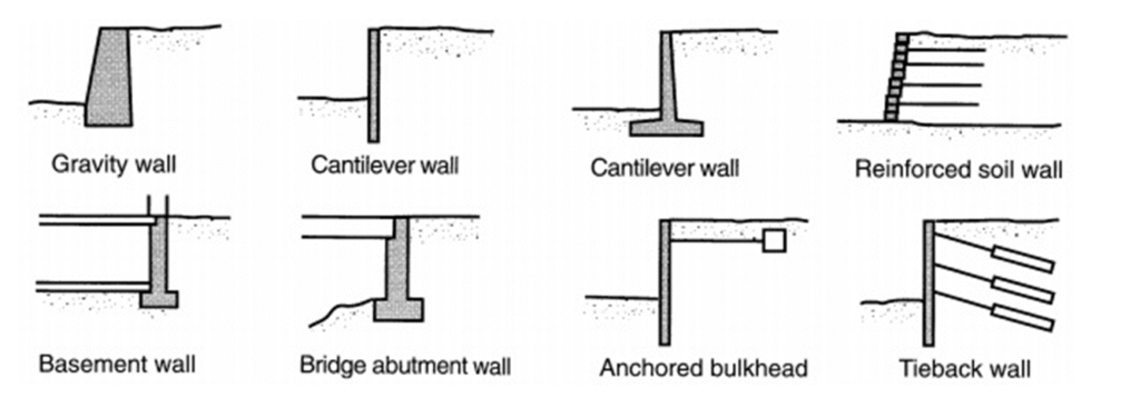
Types of Retaining Walls
Retaining walls come in a variety of forms. The main types used in practice are listed below:
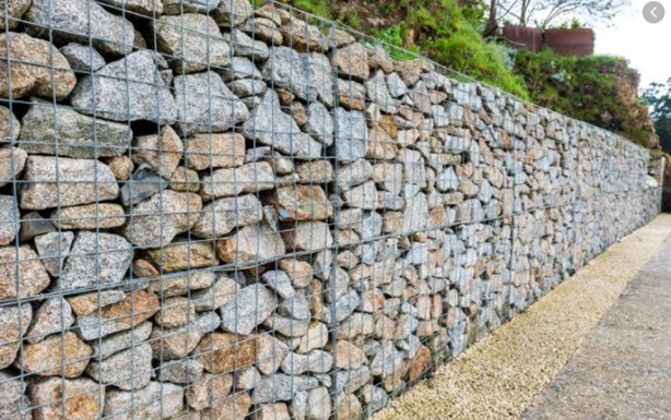
- Gabion Retaining Wall — wire mesh baskets filled with stone or rock
- Cantilever Retaining Wall — reinforced concrete wall with a vertical stem and horizontal base slab
- Post and Panel — vertical posts with horizontal precast panels spanning between them
- Precast Concrete Crib — interlocking precast units forming a crib-like gravity wall
- Sheet Piled Wall — interlocking steel sections driven into the ground — usually temporary
- Piled Retaining Wall — Contiguous — closely spaced piles with small gaps between them (unconnected)
- Piled Retaining Wall — Secant/Soldier — overlapping or interlocking piles forming a connected, watertight wall
- Reinforced Earth — layers of geosynthetic reinforcement embedded in compacted fill with a facing
- Soil Nailing — bars drilled into existing ground and grouted in place, with a shotcrete face
- Masonry Retaining Wall — constructed from stone, brick, or blockwork
Retaining Wall Design Considerations
The following factors must be assessed before selecting a wall type and commencing design. The design will be guided and governed by a Geotechnical Engineer, and depending on the wall type selected, will be designed by both geotechnical and structural engineers.
- Type of soil
- Presence of ground water
- Retained height
- Surcharge load
- Retained length
- Access to site
- Aesthetics
Failure Mechanisms of Retaining Walls
To design a retaining wall, we must first understand and define how it will fail. Failure modes vary depending on the wall type.
Gravity Retaining Walls
- Sliding
- Overturning
- Gross instability
- Bearing failure at base of wall
Cantilever Retaining Walls
- Sliding
- Overturning
- Gross instability
- Bearing failure at base of wall
- Flexural failure of concrete
- Shear failure of concrete
Anchored Retaining Walls
Anchored retaining walls usually fail due to gross instability. Other failure modes include:
- Tilting
- Flexural failure
- Failure of bracing
- Anchor pull out
- Tie rod failure
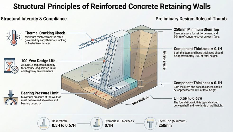
Approximate Proportions of a Cantilever Retaining Wall
The following rule-of-thumb proportions can be used as a starting point for sizing a reinforced concrete cantilever retaining wall, where H is the total wall height:
| Element | Approximate Proportion |
| Base Width (L) | 0.5H to ²⁄₃H |
| Thickness of Base (D) | 0.10H |
| Stem Thickness at Bottom (C) | 0.10H |
| Width of Toe (B) | 0.25L to 0.33L |
| Stem Thickness at Top (t) | 250 mm (reinforcement + 50 mm cover each face) |
Design Steps — Reinforced Concrete Cantilever Retaining Wall
The full design of a reinforced concrete cantilever retaining wall involves the following steps. Steps 1 to 3 (global stability) are covered in this document.
- Check Overturning Moment (FOS > 2.0)
- Check Sliding (FOS > 1.5)
- Check bearing pressure under footing
- Check wall thickness for shear
- Design wall stem for bending
- Check the length of base
- Check footing thickness for shear (as if a ground beam)
- Design reinforcement — 10 mm bars at 200 mm centres usually suffices; early thermal cracking generally governs
Required Design Parameters
Design standards will depend on the environment in which the asset is located:
- AS 4678-2002: Earth Retaining Structures
- AS 5100 Part 5: Structural design of concrete retaining structures in the Rail and Highway environment
The following parameters are required before commencing design. Parameters marked with (*) are provided by the geotechnical engineer, ascertained by borehole data or historical data. In the absence of site data, a structural engineer may make a conservative estimation for preliminary design.
| Parameter | Description |
| *qall | Soil Bearing Capacity (kPa) |
| *fo | Coefficient of Soil Friction |
| *γs | Unit Weight of Soil (kN/m³) |
| γw | Unit Weight of Water (kN/m³) |
| γc | Unit Weight of Concrete (kN/m³) |
| w | Surcharge (kN/m²) |
| *GWL | Ground Water Level |
| h | Height of Surcharge / Wall (m) |
| fcu | Strength of Concrete (MPa) |
| fy | Strength of Steel (MPa) |
Forces Acting on a Retaining Wall
The stability of a retaining wall depends on the forces and weights acting on it. The key forces to consider are the active earth pressure from the retained soil, any surcharge load, the self-weight of the concrete wall, and the weight of soil sitting above the base heel.
The coefficient of active and passive earth pressure (ka and kp) are determined using the Rankine or Coulomb formula.
| Both the Overturning check and the Sliding check are weight-based checks. Important: Any beneficial (stabilising) weights are factored DOWN by 10% — this is the Gap Factor, applied to allow for uncertainty in dimensions and material properties. |
Overturning Check
To satisfy the overturning moment stability, the following criterion must be met:
| RM / OM ≥ 2.0 RM = Resisting Moment — due to the weight of the retaining wall OM = Overturning Moment — due to lateral earth pressure |
Sliding Check
To satisfy the stability check against sliding, the following criterion must be met:
| RF / SF ≥ 1.5 RF = Resisting Force SF = Sliding Force |
Ground Bearing Check
The ground bearing check usually governs the design. The soil under the toe of the foundation works hard to resist vertical loads, sliding shear, and provides passive resistance to sliding.
The applied bearing pressure on the soil is calculated by taking into account all effects bearing simultaneously on the soil. For the footing to be safe in bearing, the maximum working load must be less than the allowable soil bearing pressure:
| qmax < qall Where: P = Total Weight M = Overturning Moment qmax is calculated from the combined effects of P and M acting on the base |